Sunday, 8 May 2011

Tom Senior Shapers & Planers

Tom Senior Shapers & PlanersFirth Planer   Senior Milling Machines   Senior Lathes
Tom Senior, of Atlas Works, Hightown, Liversage, Yorkshire, England, began in trade by producing machines originally designed and manufactured by Arthur Firth of Cleckheaton. He also had a thriving business both factoring and manufacturing a variety of useful castings and tools designed to appeal to the model engineer, schools and technical-training institutions. Senior's range of products quickly expanded and, by the time World War Two started in 1939, a number of different drills, several varieties of shapers & planers in sizes 00, 0, 1, 2 and 3 as well as light-duty horizontal millers and a lathe were all available. The larger machines could be bought either as complete, working tools or in various stages of completion for final fitting and assembly by the purchaser.  The shapers, planers and drills appeared not to survive the conflict and, by the time peace returned in 1945, Senior (who always operated from an almost cottage-industry site), was concentrating on his new range of horizontal, vertical and universal milling machines. There was also a close relationship between Firth and Hesketh-Walker, a Liverpool-based manufacturer or distributor, whose hand-operated planers appear to have been identical. However, who made what, and sold to whom, is not yet clear.Continued below:


Tom Senior No. 1 hand-operated shaper. This model was identical to the No. 2 (below) but in place of a T-slotted table, elevated by a screw, had a simple angle plate held by bolts passing through vertical slots into the knee bracket. The stroke of the ram was 8 inches and the cross traverse of the head a very useful 12.5" - this being much greater than that of the later powered machines of 10-inch stroke produced by Alba and Elliot, etc. The T-shaped "table" of the No. 1 measured 8" x 7" x  6.5" and could be adjusted vertically through a range of 4"; the maximum clearance between the table surface and a cutting tool was 9 inches.
In 1939 the complete machine was offered at £16 : 10s : 0d (about four weeks' wages at the time) or as a set of casting "in the rough" for £4 : 5s : 0d  or "accurately planed" for £8 : 10s : 0d. - both prices including a set of blueprints.
Additional machining work could be carried out for the impecunious purchaser of the casting sets; turning the end of the ram and graduating and indexing it for angle work was priced at ten shilling (equal to a naughty weekend away in Blackpool); cutting the traversing and tool box screws and supplying threaded gunmetal nuts was fifteen shillings and, if the optional self-act to the head-traverse feed was required, a "machine-cut" pinion could be supplied (for the price of a Saturday of overtime in the mill) at seven shillings and sixpence.
Both models were carefully thought out; the ram drive was by an apparently unique-to-senior rack and quadrant arrangement (but later also used on Perfecto shapers) and the body of the machine was cored with a two-inch diameter hole that allowed shafts to protrude through under the clapper box - and so enable a slot to be cut anywhere along their length.. The table and handwheel assembly could be detached from the body of the machine to reveal a machined and slotted vertical face that offered a further range of opportunities to mount special or difficult-to-handle work.
Besides these hand-operated shapers Senior also manufactured a shaper attachment designed to fit on the bed of a lathe - and take its drive from a slotted crank plate that bolted to the faceplate; details of this interesting device can be found lower down the page.
Continued below:


Tom Senior "Shaping Attachment" designed to fit on the bed of a lathe and take its drive from a slotted crank plate bolted to the lathe's faceplate (note the dovetail ways on the rear support).
The slot in the crank plate (just visible in the illustration) allowed the length of the stroke to be adjusted.
Senior proved a range of popular fittings but could, on submission of a suitable sketch, make the unit to fit almost any section of bed.
The shaper was made in five sizes:
Size 1   Stroke 5"    Traverse travel 8"    to suit lathes of 3.5" to 4" centre height
Size 2   Stroke 6"    Traverse travel 10"  to suit lathes of 4" to 4.5" centre height
Size 3   Stroke 8"    Traverse travel 12"  to suit lathes of 4.5" to 5" centre height
Size 4   Stroke 9"    Traverse travel 14"  to suit lathes of 5" to 6" centre height
Size 5   Stroke 10"  Traverse travel 16"  to suit lathes of 6" to 7" centre height


Senior No. 2 Self-acting Hand Shaping Machine. Identical in size and capacity to the No. 1 the No. 2 featured a wider T-slotted table of 12" x 7" elevated by a proper screw and nut.


The Rack and Quadrant drive - a feature that seems, at the time, to have  been unique to Tom Senior


Tom Senior Nos. 1 and 2 Planer with automatic cross feed.
Continued:Today, unless they are located in a particularly remote area, without access to larger milling machine,  planers are almost unknown in the workshops of all but the keenest and most knowledge amateur engineers. However, as a means of economically removing metal from large components they are still unbeatable and many massive examples, some the largest machine tools ever constructed, are still in industrial use. One particularly effective development is the "plano-miller" - a planer with powered cutting heads fastened to the bridge and uprights and able to perform miracles of metal removal on huge jobs.
Despite their rarity many enthusiasts still seek out the smaller versions - the bench job in particular are keenly sought after and command a high prices - and not just for their novelty, but to do a serious job of work at low cost. Although the delightful movements of a powered machine are a delight to behold, the hand-operated versions also provide an extra glow of pride as the owner enjoys the satisfaction of complying with the latest government health edict (issued, you may have noticed, by an overweight politician) on regular exercise and sin-free living.
The Senior planers illustrated on this page, all from a more gentlemanly age (and almost certainly as originally produced by Arthur Firth of Cleckheaton) were available as either complete units - or as rough or planed castings. Five sizes were listed: 00, 0, 1, 2 and 3. No 00 could machine work up to 12" long, 6" wide and 4
1/2" high. The No. 0 took material up to 16" by 6" by 41/2"; the No. 1 18" by 7" by 5"; the No. 2 20" by 7" by 5" and the No. 3 24" by 10" by 7".
Whilst the No. 1 and No. 2 were essentially the same machine they did have tables of a different size - whilst the No. 3 was a much more robust model that must have been at the very limit for hand-powered operation. 
Prices for the time were modest: the No 1, which could machine a component 12" long by 6" wide and 4.5" deep, was £15 : 19s : 0d with auto-feed (or without at a saving of £2 : 4s ; 0d) whilst the larger No. 2, with a 20" by 7" by 5" capacity, was £18 : 14s : 0d - or £15 : 8s : 0d if you wanted to apply the cross feed by hand.
In casting form the No. 2 and No. 3 machines were respectively £2 : 10s : 0d and £4 ; 0s : 0d in the rough - and £7 : 10s : 0d and £9 : 0s : 0d with the major components ready planed. However, it would have been a brave man who smuggled one of these through his kitchen,  past his better half - and down into the garden shed for home completion..


Tom Senior No. 3 Planer with self-act on the cross traverse.


More than likely by Arthur Firth, this diminutive model from their range probably dates from the first decade of the 20th century.
Despite it's small size, with just an 18" x 6" table and a maximum clearance of 6 inches between tool and top surface, this is a heavily-built machine and can only just be lifted by one man with the table removed.
Like most if its kind (and many shapers) the clapper box can be rotated a little each side of central to allow clearance on the return stroke when using certain shapes of cutting tool. However, not so common is the provision of a tapered pin to set the whole of the tool assembly vertical again if had been angled over.
Able to work in either direction - by flipping a pawl over - the cross feed rate can be altered by sliding the vertical actuating arm along the two parallel horizontal bars. The mechanism appears to be of a more modern design than the planer--and is interesting. The drive is tripped by an adjustable stop, set in a T-groove machined along the edge of the table, and by rotating the arm that hits the stop the mechanism can be set to feed at either the beginning or towards the end of the stroke. The component is hinged, and with a cut-away that allows it to 'fold' in one direction, yet remain upright in the other  - so ensuring that the feeds mechanism operates in one direction only. However, as found, the device lacks a spring to return it to return to the upright position - and may be incomplete.
All sliding surfaces are frosted - even the sides of the clapper box - and, as most are still intact, the planer can have seen little use. The vice also appears to 'belong' to the machine, with the bolt holes lining up with the slots in the bed. The moveable jaw lock in grooves in the base of the vice, allowing the operator to set its position quickly and easily.
Included with the machine when found in a house-clearance sale where a number of original cutting tools, a number of them bearing the maker's name
W. Marples & Sons with a "shamrock" trademark.
A larger Firth planer can be seen here.


Particularly elegant and delicate casting (American in quality) and, at the near end, can be seen the "inverted" V-ways to guide the carriage. Note the similarities to  the Tom Senior Models Nos. 1 and 2 and also to the Hesketh-Walker.


On this model the designer took care to extend the cross-had ways to allow the machining on components wider than the table


Typical of its era the clapper box was lightly built.


Nuts and bolts from the pre-WW1 era can be recognised by their unnecessarily generous proportions


Tapered location pin for the clapper box


The hinged stop used to reverse the feed to the bridge-mounted toolpost


Simple indexing mechanism used to move the cutting tool across the bridge


The tool-head stroke length could also be altered by position the actuating arm


E-MAIL   Tony@lathes.co.uk
Lathes.co.uk home   Machine Tool Archive   Machine Tools For Sale & Wanted
Machine Tool Manuals   Machine Tool Catalogues     
 
Tom Senior Shapers & PlanersSenior Milling Machines   Senior Lathes


lathes machine


Ames Lathes - USA
   Ames Millers   Ames Triplex Multi-Function Machine   Photographs Ames 1940s to 1960s   Circa 1835/80 Ames Chicopee Lathe

Although no Operator's Manual was ever produced for Ames lathes, a collection of interesting Sales Catalogues is available. Please email for details
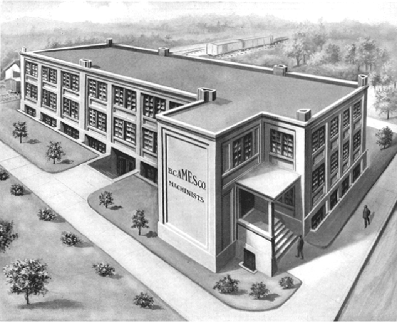
When Bliss Charles Ames opened his machine-tool works on Ash Street in Waltham, Ma. in the late 1890s, he was joining an exclusive club of manufacturers* who, though they produced relatively few machines, made a significant contribution to improving the standards of quality and precision employed in American manufacturing industry. Amongst Ames's fellow high-class machine-tool makers in Waltham were Stark, the American Watch Tool Company, The Waltham Machine Works, Wade and F. W. Derbyshire - with others, including  Pratt & Whitney, Rivett, Cataract, Hardinge, Elgin, Hjorth, Potter, Remington, Sloan & Chace and Pearce in other parts of the U.S.A.
Ames quickly became well-known (as the B.C. Ames Co.) for a range of very accurate machine tools and precision measuring equipment; they did not produce a huge number of machines - the specialised marked for precision bench lathes and millers was relatively small and the competition fierce. In the early 1920 an average of one hundred No. 3 lathes were being produced each year, a number that fell to a low of just two or thee at the height of the depression in the early 1930s; sales picked up to nearly fifty a year during the middle to late 1930s followed by an explosion in growth during the years of World War 2 when, if the serial numbers are to be believed, as many as 806 left the factory between 1942 and 1943. The entire range of No. 3 and EH3 Bench Lathes, Bench Millers, Slotters and Shapers were all made until 1957, when production of the lathes only appears to have been continued using dual Stark and Ames branding - the catalogs from that point on (if not the lathes) carrying the names of both companies.
Today the Ames brand still thrives in the precision engineering field and concentrate on high-quality measuring and inspection equipment.
* includ
ing:
Levin, Bottum, The American Watch Tool Company, B.C.Ames, Bottum, Hjorth, Potter, Pratt & Whitney, Rivett, Wade, Waltham Machine Works, WadePratt & Whitney, Rivett, Cataract, Hardinge, Elgin, Remington, Sloan & Chace, and (though now very rare) Frederick Pearce, Ballou & Whitcombe, , Sawyer Watch Tool Co., Engineering Appliances and Fenn-Sadler the "Cosa Corporation of New York" and UND. 


Ames 83/8" x 21" precision bench lathe 1900 - 1930The small bench machine illustrated above, typical of an Ames lathe, was available with a complete range of screw and lever-feed slides, different tailstocks, various quick-release collet fittings for the headstock spindle, relieving and milling attachments and special accessories for production engineering.
Like many other Precision lathes the Ames' 3-step cone pulley had its smallest diameter by the spindle nose - so allowing the front bearing to be increased in size and surrounded by a greater mass of supporting metal.
Unusually, the spindle carried  two rings of indexing holes around the larger of the two pulley flanges - and a further ring of holes around the smaller flange designed to assist in the removal of chucks and collets, etc., from the spindle nose.
Although the beds carried serial numbers, Ames claimed that any headstock, bed and tailstock combination would line up accurately, so allowing the easy transfer of specialised production equipment from machine to machine within a factory.


Broaching a hexagon collet using a rack-feed tailstock.
Broaching is a fairly unusual process to carry out on a small lathe but it is perfectly possible, given sharp tools and some care, to make a success of it.
The indexing holes which equipped the headstock of the Ames (and many other lathes) were, of course, an essential part of the procedure.


Drilling acetylene torch nozzles with the Tip Drilling Attachment


The Three-bearing Head model in use at the L.S. Starrett works in Athol, Mass. where over one hundred similar Ames bench lathes were employed.


Once a commonly available accessory for small lathes, the tailstock-mounted indexing turret was a simple and economical way of producing small batches of components.
An ordinary screw-feed tailstock barrel would have slowed the process up more than somewhat, but if lever or rack-operated, and with light work, respectable rates of production could be achieved with very simple tooling.


"Half-open" Tailstock in use in conjunction with a two-toolholder lever-feed cross slide.


Six-station, hand-indexing Turret  and Lever-action Cross Slide.
The indexing plunger by the rear pulley flange is clearly visible.


Headstocks


Section through an early Ames bench-lathe headstock.
The headstock was available in two sizes (but of the same centre height) to take collets with a maximum capacity of either 5/8" or 1" with spindle bores of 3/4" and 1
1/8" respectively. The collets could be of either the draw-in type, or closed by a lever mechanism.
The hardened spindle was machined from a solid bar of alloy steel, case hardened then ground and lapped. This method of production produced a spindle which was hard on the outside but "soft" within - and consequently extremely tough.
The outside of the spindle front was ground to a 4 degree taper onto which faceplates, chucks and the larger sizes of step collets and their closers could be drawn. The inside of the spindle nose was ground to an 11 degree taper to seat and close collets.
The cast-iron headstock bearings, oil-grooved and finely lapped, were parallel on the inside and tapered on the outside. Adjusting nuts, acting on square-section threads, drew the bearings into tapered seats within the headstock casting and compressed them concentrically.
The combination of a hardened steel spindle running in cast-iron bearings was a proven method of obtaining long life and cool running; the spindle end thrust was taken by a ball race, positioned immediately behind the spindle nose, and carrying an adjusting ring to limit end play. The location of the thrust bearing, immediately behind the chuck on the "end" of the spindle, was unknown on any other lathe of this (precision) type.
The larger of the pulley flanges carried  two rings of 60 and 72 indexing holes, with a further ring of larger holes around the smaller flange which designed to assist in the removal of chucks and collets, etc., from the spindle nose.
Later Ames lathes followed the lead of Wade in fitting their bench lathes with precision ball-bearing headstocks - the lathe illustrated here is so equipped.


3-jaw chuck showing the backplate with its tapered seat which drew onto the 4 degree taper on the outside of the headstock spindle.


"Step chuck" with its external closing adaptor.
Step chucks were used to hold diameters larger than the headstock spindle would admit. They were made of cast iron and  supplied with a 1/4" hole drilled through the centre.
To use them, the face was turned out to a suitable depth and diameter to accommodate the workpiece, which was then tightly gripped as the collet was drawn back against the closing ring. They were made in 2" and 4" diameters for both the 5/8" and 1" capacity headstocks.


The Three-bearing Headstock was designed for production work. An extension at the left-end of the headstock carried a third bearing which supported an integral, quick-action collet opening and closing device.
The device was intended to overcome the inherent tendency of collets to draw work backwards when they were tightened, making it difficult to obtain exact depth setting on repetition work. In this design the collet remained "stationary" whilst, ingeniously, the headstock spindle moved forwards and backwards to tighten and release it.
The mechanism was foot-operated, so leaving the operator's hands free to manipulate the compound slide rest, or other attachments, and feed material into the collet.


End view of bed showing the double ring of 60 and 72 indexing holes on the spindle-pulley flange.


Slide Rests & Attachments


The Ames Compound Slide Rest, a substantial affair which weighed 16 lbs, had finely made feed screws of 0.354" diameter, with milled threads of square form running though bronze nuts.
The top slide could be swivelled through 50 degrees either size of zero and the 4
5/8" diameter base was clamped by two screws engaging with a circular T slot in the 3.75"-travel cross slide.
Whilst the top slide has the usual generous amount of travel for this type of lathe (5.5"), the cross slide was limited to just 3.75"
The micrometer dials, with bevelled edges, could be zeroed but, like many other lathes of the time, were far too small, being just over 1" in diameter.


Lever-action cut-off or "forming slide", used to part off, or turn work to the "form" of a cutting tool.


milling machine toolsmilling machine tools

        milling machine tools


Company Name: Chengdu Longren Tec., Ltd. 
Company Address: Rm. C, 5th Floor, Diamond Building, Jinjiang International Business Mansion, East Li, Chengdu, Sichuan, China 
City/Province: Chengdu/Sichuan 
Country/Region: China 
Zip/Postal Code: 610021 
Telephone Number: 86-28-85456704  Local Time
Fax Number: 86-28-85456703 
Contact Person: Ms. Claire 
Showroom: http://cdlrkj.en.made-in-china.com  
Homepage: Click Here 


 Mlling machine


Packing:  fully enclosed wooden case
Model NO.:  VT1055
Standard:  ISO International Quality Control
Productivity:  300 Sets/Per Year
Unit Price/Payment:  L/C, TT
HS Code:  8457101000
Trademark:  DATAN
Origin:  made in China
Min. Order:  1 set
Transportation:  by sea
Controlling Mode:  CNC
Precision:  High Precision
Type:  Heavy-Duty Machine Tool
Automatic Grade:  Automatic
X/Y/Z Axis Travel/Mm:  1000*560*610
Worktable Size/Mm:  1000*560
Guide Rail:  Box Type Guide Rails
Controller:  Fanuc
Export Markets:  North America, South America, Eastern Europe, Southeast Asia, Mid East, Eastern Asia, Western Europe